FibroCeram Materials FibroCeram Materials

2026 Best Types to Enhance Resistance to Thermal Shock

Time:2026-09-26 Author:Aria
0%

Thermal shock can crack a furnace lining, chip a ceramic seal, or distort a component when temperatures change too quickly. In 2026, choosing materials for these conditions means looking beyond maximum service temperature. A material must also handle rapid heating, sudden cooling, repeated cycles, and the temperature differences that develop across its surface. Those details matter on real equipment.

This guide explores material types that can help Enhance resistance to thermal shock in industrial environments, including advanced ceramics, refractory materials, selected alloys, and engineered composites. Each offers a different balance of thermal expansion, conductivity, strength, and toughness. Low expansion can help limit stress, but it does not guarantee durability. Geometry, joints, surface finish, installation, and exposure to moisture can change the result. Small details count.

There is no universal winner. A ceramic that performs well in a controlled test may fail in a damp, unevenly heated process line. That gap deserves attention. We compare useful material characteristics and practical selection factors, while noting where specifications and application testing are essential. Check manufacturer data, operating conditions, and relevant test methods before making a final choice. The best option is the one validated for the actual heating and cooling cycle—not simply the one with the highest temperature rating.
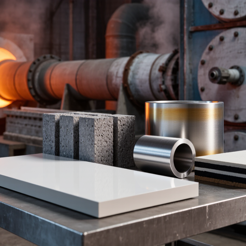
2026 Best Types to Enhance Resistance to Thermal Shock

How Thermal Shock Resistance Is Measured

Thermal shock resistance is measured by exposing a material to rapid temperature changes, then checking how well it withstands the stress. A test may heat a ceramic tile in a furnace and move it into cool water. The temperature difference, transfer time, and number of cycles must be recorded. Small changes in these conditions can alter the results.

Researchers inspect samples for visible cracks, chips, or warping after each cycle. They may also measure strength before and after testing, since hidden damage can weaken a part without obvious signs. For reliable comparisons, samples should have similar dimensions and surface finishes. Test reports should state the heating and cooling rates, hold times, and inspection method. There is no single result that suits every use. A thin component may respond differently from a thick block, even when both use the same material. That detail is easy to overlook. Results are most useful when test conditions match the temperature swings and constraints expected in service.

2026 Best Types to Enhance Resistance to Thermal Shock

How Thermal Shock Resistance Is Measured

The chart compares representative room-temperature linear thermal expansion coefficients (CTE); values vary by grade and test conditions. Lower CTE can reduce thermal strain, but it does not alone determine thermal-shock resistance. Resistance is commonly evaluated by exposing specimens to controlled temperature changes, then recording the critical temperature difference (ΔT) or number of cycles before cracking or failure.

Material Families That Withstand Rapid Temperature Changes

Thermal shock resistance depends on more than a material’s maximum service temperature. A part must handle rapid heating or cooling without cracking. Low thermal expansion helps limit internal stress, while good thermal conductivity spreads heat more evenly. Dense silicon carbide often suits repeated temperature swings because it conducts heat well and remains strong at high temperatures. Alumina offers hardness and dependable electrical insulation, though thick sections may develop steep temperature gradients. Fused silica expands very little, making it useful where dimensional stability matters. No material is immune to damage.

Tips: Match the material to the actual temperature cycle, not just the peak temperature. Test the finished shape when possible. A sharp corner or uneven wall can become the weak point.

Zirconia can provide strength and thermal insulation, but its low conductivity may increase temperature differences across a component. That trade-off is easy to miss on a data sheet. In practical selection, consider part thickness, surface finish, heating rate, cooling method, and contact with other materials. A small test piece can reveal flaws that specifications alone cannot. Even then, results may differ in larger parts, so leave room for uncertainty.

Microstructures That Help Prevent Thermal Shock Damage

Microstructure determines how quickly heat moves and where cracks begin. Fine, uniform grains reduce large stress concentrations, while elongated grains can deflect cracks and bridge them across grain boundaries. This is one reason silicon nitride ceramics often use interlocking, elongated grains: a crack may turn or slow rather than travel straight through the body. Small details matter.

For scale, R. G. Munro’s evaluated material-property study of sintered alpha-alumina reports thermal conductivity near 33 W/m·K at 20°C. That value is a benchmark, not a guarantee of thermal-shock performance; porosity, grain boundaries, and part geometry also affect heat flow. Dense, well-bonded structures can carry heat away from a hot surface, while controlled gradients in composition or porosity can reduce abrupt temperature differences through a component. ASTM C1525 provides a standardized method for comparing ceramic thermal-shock resistance, but test results depend on the specimen and quench conditions.

A caveat: finer grains are not automatically better. Excessive porosity can weaken a part, yet a carefully designed pore structure may lower stiffness and ease local stress. It’s a trade-off. In practice, inspect grain shape, boundary phases, and density alongside conductivity and fracture toughness. A polished cross-section can reveal features that a single headline property misses.

Design and Processing Methods That Improve Resistance

Thermal-shock resistance starts with controlling temperature gradients, not simply choosing a “tough” material. ASM’s Engineered Materials Handbook, Volume 4, reports typical thermal-expansion values near 0.5 × 10⁻⁶ K⁻¹ for fused silica, 3.2 × 10⁻⁶ K⁻¹ for silicon nitride, and 8 × 10⁻⁶ K⁻¹ for alumina. Lower expansion can reduce mismatch stress, but strength, porosity, and part geometry still matter. Small details matter.

Design rounded internal corners and gradual wall transitions to reduce local stress concentrations. Avoid thick-to-thin sections where possible; a hot surface can expand while a cooler core resists it. Processing choices help, too. Controlled firing, uniform cooling, and careful control of residual porosity improve consistency between parts.

A dense surface over a porous core may behave unpredictably, so inspect the full section, not just the finish. ASTM C1525 and C1171 provide established methods for evaluating thermal-shock behavior in advanced ceramics and refractories. Compare results only when specimen size, heating, and quenching conditions match. That caveat is easy to overlook. Test representative parts, because a laboratory coupon may not reproduce real edges, joints, or operating cycles.

How to Choose a Thermal Shock-Resistant Material in 2026

How to Choose a Thermal Shock-Resistant Material in 2026

Start with the temperature change, not the material name. A part moved from a hot furnace into cool air faces a different shock than one splashed with water. Check peak temperature, heating and cooling rates, cycle count, and part thickness.

ASM Handbook property tables put typical room-temperature thermal conductivity near 25–35 W/(m·K) for dense alumina and about 120 W/(m·K) for many silicon carbide grades.

These are grade-dependent figures, not guarantees. Higher conductivity can spread heat faster; low expansion and strong resistance to cracking also matter. Thin corners and drilled holes can still fail.

For repeated service, compare candidate grades under the actual temperature range and cooling medium. ASTM C1171 provides a quantitative method for assessing thermal shock and cycling effects in refractories.

Ask suppliers for test conditions and post-cycle strength, not just a “thermal shock resistant” label. A small coupon may not predict a thick, constrained component.

That gap matters.

Tips:

Sketch the real part, including sharp edges and mounting points. Test a representative sample through realistic cycles, then inspect for cracks and measure strength.

One caveat: lab conditions can flatter a material. Recheck the choice after installation if airflow, contact, or cooling rates differ.

FAQS

What does thermal shock resistance measure?

It measures how well a material survives rapid temperature changes. A ceramic tile may move from a hot furnace into cool water. Testers record the temperature difference, transfer time, and cycle count.

What damage should testers inspect after each cycle?

They should look for cracks, chips, and warping. Hidden damage can exist without visible marks. Strength testing may reveal this weakness.

Why must test conditions be recorded carefully?

Small changes can alter the result. Heating rate, cooling rate, hold time, and inspection method all matter. A quick transfer is not the same as a slow one.

Do thin and thick parts respond similarly?

Not necessarily. A thin component may cool quickly, while a thick block keeps heat inside. Geometry can change stress patterns significantly.

How does microstructure affect thermal shock damage?

Microstructure controls heat movement and crack direction. Fine, uniform grains can reduce stress concentrations. Elongated grains may turn or slow cracks.

Is higher thermal conductivity always better?

No. Conductivity helps move heat away from hot areas, but it does not guarantee resistance. Porosity, grain boundaries, and shape also affect performance.

Can porosity improve thermal shock resistance?

Carefully controlled pores may lower stiffness and ease local stress. Excessive porosity can weaken the part. The balance is easy to misjudge.

How can researchers make fair comparisons?

They should use samples with similar dimensions and surface finishes. Matching test conditions to real service is important. Otherwise, the comparison may mislead.

What properties should be examined together?

Inspect grain shape, boundary phases, density, conductivity, and fracture toughness. A polished cross-section can reveal hidden structural details. One headline value is not enough.

Conclusion

This article explores how thermal shock resistance is evaluated and why it matters when materials face sudden changes in temperature. It explains key measures such as thermal expansion, conductivity, strength, and resistance to cracking, then compares material families—including ceramics, glass, metals, and composites—that can tolerate rapid heating and cooling. The discussion also looks at how grain structure, porosity, and other microstructural features influence damage, helping readers understand why materials with similar compositions may perform differently.

Practical design and processing choices can further improve performance, from controlling component geometry and surface finish to managing fabrication and cooling conditions. The article concludes with a framework for selecting a suitable material in 2026 based on operating temperatures, thermal cycling, mechanical loads, cost, and maintenance needs. By weighing these factors together, engineers can make informed choices to Enhance resistance to thermal shock in industrial environments and support reliable, durable equipment operation.

Aria

Aria

Aria is a dedicated marketing professional with a deep passion for innovative strategies and a keen understanding of our company's product offerings. With a wealth of experience in the industry, Aria excels at crafting engaging content that highlights the unique features and benefits of our......